GB السائل (النفط)- coold عالية الطاقة موصل DCCharging المواصفات الفنية | |||||||
المعلمات الفنية لموصل الشحن | |||||||
بارامترات كهربائية | تعريف المنفذ | العاصمة ± | PE | A ± | CC1 | CC2 | S ± |
مواصفات الأسلاك (mm²) | 30 | 6 | 1.5 | 0.5 | 0.5 | 0.5 | |
قطر طرف الاتصال (مم) | Φ12 | Φ6 | Φ3 | Φ3 | Φ3 | Φ3 | |
جهد التشغيل المقنن (العاصمة) | أقل V | 0-30 فولت | 0-30 فولت | 0-30 فولت | 0-30 فولت | 0-30 فولت | |
التصنيف الحالي | 100A (عندما لا يعمل نظام التبريد السائل) | / | 10 أ | 2A | 2A | 2A | |
أقصى تيار العمل المستمر | 600A (طول الخط وسعة الإدارة الحرارية) | ||||||
القطر الخارجي للكابل | 30x x x x ² (سلك أرضي 6 مم مصدر طاقة إضافي 1.5 مم ²) | ||||||
وزن الموصل. | (بدون كابل) | ||||||
مقاومة العزل | • MΩ بين محطة التيار المباشر الموجب والسالب ومحطة البولي إيثيلين (اختبار الجهد V D C) | ||||||
تحمل الضغط (50 هرتز ، تيار متردد) | اختبار بعد توصيل الأسلاك: ① جهد المقاومة بين العاصمة و V DC 1 دقيقة ؛ ② DC ، DC ، PE ، S ، S ، A-voltage ، ③-V DC 1 دقيقة ؛ جهد مقاومة من من من من من من من V D C 1 دقيقة بين S ، S-، A و-؛ ④ S ،-، CC1 ، A-اثنين مقاومة الجهد من ، V D S 1 دقيقة ؛ | ||||||
ملاحظة: القطر الخارجي والمنطقة الأساسية للكابل يمكن تصميمها وتخصيصها وفقًا للاحتياجات الفعلية للعملاء | |||||||
الخواص الميكانيكية | خدمة الحياة: | Force مرات | |||||
قوة السحب والقابس: | 120 ن | ||||||
قوة القفل: | 200N | ||||||
المعلمات البيئية | مستوى الحماية قبل الإدراج: | IP54 | |||||
درجة الحماية بعد الإدراج: | IP55 | ||||||
IP67 | |||||||
درجة الحرارة المحيطة: | -30 ℃-50 ℃ | ||||||
درجة مثبطة للهب لمواد العزل: | UL94 على | ||||||
مواد | السكن: | اللدائن الهندسية (PA66 المقاوم للحرارة أو الكمبيوتر المقاوم للحرارة) | |||||
طرفية: | النحاس ، سطح مطلي بالفضة | ||||||
أجزاء الختم: | مطاط سيليكون | ||||||
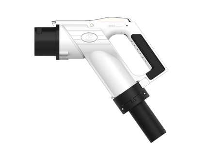
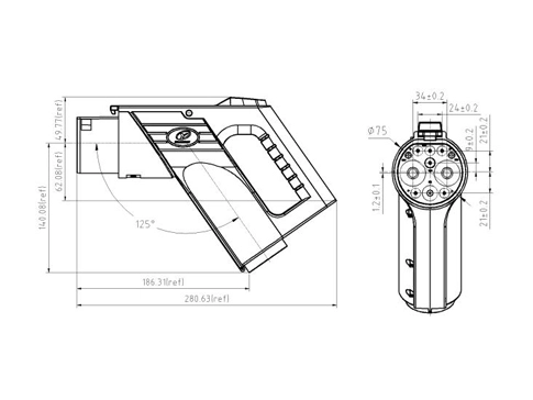
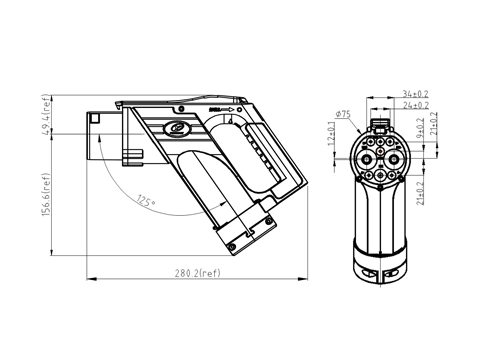
مظهر موصل الشحن | شكل! شكل واجهة موصل سائل (زيت) مبرد بالتيار المستمر (جيجابايت/T-الشحن من من من من من من من من من من من من من من من جهة ومن جهة أخرى) | ||||||
تعريف الواجهة | يوضح الشكل التالي الرسم البياني لواجهة صف الطاقة النحاسية ، واجهة تسخير سلك الإشارة وواجهة خط التبريد بين خط الموصل ونهاية الوبر. الهيكل التالي هو تصميم مخصص بشكل عام. | ||||||
وحدة تبريد متوسطة السائل (مجموعة وحدة تبريد HPC) | |||||||
المعايير الفنية | الجدول 1: جدول المعلمات التقنية | ||||||
الحجم | × من من من من ؟ ؟ | قوة تبديد الحرارة | 3.0KW @ 4L/دقيقة. 700m 3/ساعة | ||||
جهد الإدخال | DC12V | قوة | ≤ W | ||||
تبريد متوسط | زيت السيليكون ثنائي ميثيل دي-تيرت-بوتيل-p-ميثيلفينول مبرد f8016 Fuchs قذيفة E4 (-40 ~ 85 ℃) | تدفق التبريد | 4 لتر/دقيقة @ 450Kpa | ||||
ضغط إمدادات المياه | 0.6Mpa | ضغط العمل | 0 ~ 0.7MPa | ||||
درجة حرارة العمل | -40 ℃-50 ℃ | حجم وعاء التوسع | ، إل | ||||
الضوضاء | ≤ 60 ديسيبل (أ) | مستويات الحماية | IP 68 | ||||
الوزن | 7 أو | وضع الاتصال | بناءً على Modbus ،/ 232 | ||||
طريقة التحكم | التشغيل الآلي الكامل | العمر الافتراضي | في ح | ||||
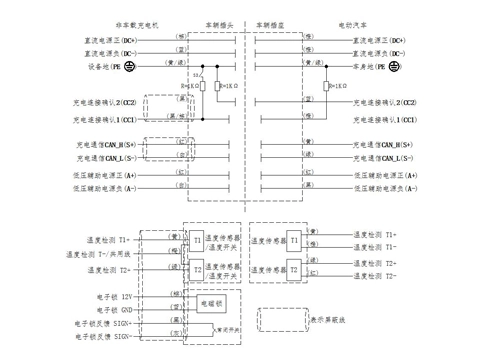
تعريف دبوس الأسلاك | الجدول 2 تعريفات دبابيس الأسلاك | ||||||
رقم الطلب | الاسم | منطقة مقطعية من سلك (mm²) | نموذج المحطة | ملاحظات | |||
1 | أرضية الإشارة | 0.5 | E0508 | CI | |||
2 | (أ) الاتصالات)/ 485-A | 0.5 | E0508 | CI | |||
3 | أ-(من الاتصالات) 485-B | 0.5 | E0508 | CI | |||
4 | تمكين مروحة | 0.5 | E0508 | التحكم في طاقة المروحة | |||
5 | مروحة تمكين- | 0.5 | E0508 | التحكم في طاقة المروحة | |||
6 | 12 فولت/24 فولت | 1.0 | TVS1.25-4 | مزود طاقة للتحكم | |||
7 | GND | 2.5 | TVS2-4 | مزود طاقة للتحكم | |||
8 | تمكين المضخة | 0.5 | E0508 | التحكم في طاقة المضخة | |||
9 | تمكين المضخة- | 0.5 | E0508 | التحكم في طاقة المضخة | |||
10 | مضخة 12 فولت/24 فولت | 1.0 | TVS2-4 | التحكم في طاقة المضخة | |||
11 | مروحة: 12V / 24V | 1.0 | TVS2-4 | مصدر طاقة المروحة | |||
احتياطات السلامة | يأخذ هذا المنتج السائل العازل كوسيط تبريد ، إذا كان الاستبدال غير المصرح به قد يؤدي إلى انخفاض أو تلف هيكل الختم لوحدة التبريد ، أو حتى يتسبب في تلف خط الموصل. غطاء وعاء التمدد مملوء بوسط تبريد ويتم فتحه عند الضرورة. في حالات أخرى ، يكون الغطاء في حالة محكمة لمنع دخول الغبار والجزيئات الصغيرة والماء والمواد الأخرى ، وذلك لتجنب الانسداد أو حوادث السلامة. يحظر لمس اليد في عمل المنتج لمنع المروحة من إصابة اليد. لا تلمس المبرد أثناء عمل المنتج لمنع السمط. | ||||||
التنظيف والصيانة | تنظيف فقط عندما لا يتم تنشيط المنتج. تنظيف الأجزاء الكهربائية والأجزاء المتبقية بقطعة قماش جافة. لا تستخدم المنظفات ، موصل المياه ، موصل البخار مع تأثير تآكل للتنظيف. معظم أجزاء المنتج من البلاستيك الحراري ، لا تجعل المنتج يتأثر بالقوة الخارجية ، حتى لا يؤثر على الاستخدام. سر أثناء استخدام المنتج ، يجب فحص مستوى سائل وعاء التمدد بانتظام لتجنب فشل مستشعر مستوى السائل تلف المنتج وحوادث السلامة الناجمة عن الإنذار. فترة الفحص الموصى بها هي مرة واحدة في الربع. تحقق من المنتج بانتظام للتسرب. |
GB سائل (ماء)-موصل شحن تيار مستمر عالي الطاقة كوولد المواصفات الفنية | |||||||
المعلمات الفنية لموصل الشحن | |||||||
بارامترات كهربائية | تعريف المنفذ | العاصمة ± | PE | A ± | CC1 | CC2 | S ± |
مواصفات الأسلاك (mm²) | 48 | 6 | 1.5 | 0.5 | 0.5 | 0.5 | |
قطر طرف الاتصال (مم) | Φ12 | Φ6 | Φ3 | Φ3 | Φ3 | Φ3 | |
جهد التشغيل المقنن (العاصمة) | أقل V | 0-30 فولت | 0-30 فولت | 0-30 فولت | 0-30 فولت | 0-30 فولت | |
التصنيف الحالي | 125A (عندما لا يعمل نظام التبريد السائل) | / | 10 أ | 2A | 2A | 2A | |
أقصى تيار العمل المستمر | 500A (طول الخط وسعة الإدارة الحرارية) | ||||||
القطر الخارجي للكابل | ± ، Φ28 مم | ||||||
وزن الموصل. | (بدون كابل) | ||||||
مقاومة العزل | • MΩ بين محطة التيار المستمر الإيجابية والسلبية ومحطة البولي إيثيلين (اختبار الجهد في التيار المتردد) | ||||||
تحمل الضغط (50 هرتز ، تيار متردد) | اختبار بعد توصيل الأسلاك: ① جهد المقاومة بين العاصمة و V DC 1 دقيقة ؛ ② DC ، DC و PE ، S ، S ، A-voltage-AC 1 دقيقة ؛ ③ PE ، جهد المقاومة لـ 50 V AC 1 دقيقة بين S و S و S و A و-؛ Av S ، S-، CC1 ، A-2 جهد المقاومة من ، V AC 1 دقيقة ؛ | ||||||
ملاحظة: القطر الخارجي والمنطقة الأساسية للكابل يمكن تصميمها وتخصيصها وفقًا للاحتياجات الفعلية للعملاء | |||||||
الأداء الميكانيكي | خدمة الحياة: | أوقات الدرجة الأولى | |||||
قوة السحب والقابس: | 120 ن | ||||||
قوة القفل: | 200N | ||||||
معلمة بيئية | مستوى الحماية قبل الإدراج: | IP54 | |||||
درجة الحماية بعد الإدراج: | IP55 | ||||||
الجزء الكهربائي عالي الجهد: | IP67 | ||||||
درجة الحرارة المحيطة: | -30 ℃-50 ℃ | ||||||
درجة مثبطة للهب لمواد العزل: | UL94 على | ||||||
مواد | السكن: | اللدائن الهندسية (PA66 المقاوم للحرارة أو الكمبيوتر المقاوم للحرارة) | |||||
طرفية: | النحاس ، سطح مطلي بالفضة | ||||||
أجزاء الختم: | مطاط سيليكون | ||||||
تعريف الواجهة | يوضح الشكل التالي الرسم البياني لواجهة صف الطاقة النحاسية ، واجهة تسخير سلك الإشارة وواجهة خط أنابيب التبريد بين سلك الموصل ونهاية الوبر. الهيكل التالي هو تصميم مخصص بشكل عام. | ||||||
الشكل 2. رسم تخطيطي لواجهة كومة مدخل خط الموصل (كمرجع) | |||||||
وحدة تبريد متوسطة السائل (مجموعة وحدة تبريد HPC) | |||||||
المعايير الفنية | الجدول 1. جدول المعلمات التقنية | ||||||
الحجم | فاسيلي × × من (مم) | تغيير الحرارة | 1.6KW(50 ℃) | ||||
جهد الإدخال | 12 فولت/24 فولت | قوة | ≤ W | ||||
الحالي | مروحة (12 فولت) | ماكس 9A | |||||
مضخة (12 فولت) | ماكس 7A | ||||||
تبريد متوسط | محلول مضاد للتجمد (ماء جلايكول الإثيلين) | تدفق التبريد | 0-2.5L/دقيقة قابل للتعديل | ||||
إمدادات المياه الضغط | 6 بار | ضغط العمل | 0-6 بار | ||||
درجة حرارة العمل | -30 ℃-50 ℃ | حجم وعاء التوسع | ، إل | ||||
الضوضاء | ≤ 60 ديسيبل (أ) | مستويات الحماية | IP 68 | ||||
الوزن | 3.5 كجم | وضع الاتصال | بناءً على Modbus ،/ 232 | ||||
تعريف دبوس الأسلاك | الجدول 2. جدول تعريف دبابيس الأسلاك | ||||||
لا. | الاسم | منطقة مقطعية من سلك (mm²) | نموذج المحطة | ملاحظات | |||
1 | أرضية الإشارة | 0.5 | E0508 | CI | |||
2 | (أ) الاتصالات)/ 485-A | 0.5 | E0508 | CI | |||
3 | أ-(من الاتصالات) 485-B | 0.5 | E0508 | CI | |||
4 | تمكين مروحة | 0.5 | E0508 | التحكم في طاقة المروحة | |||
5 | مروحة تمكين- | 0.5 | E0508 | التحكم في طاقة المروحة | |||
6 | 12 فولت/24 فولت | 1.0 | TVS1.25-4 | مزود طاقة للتحكم | |||
7 | GND | 2.5 | TVS2-4 | مزود طاقة للتحكم | |||
8 | تمكين المضخة | 0.5 | E0508 | التحكم في طاقة المضخة | |||
9 | تمكين المضخة- | 0.5 | E0508 | التحكم في طاقة المضخة | |||
10 | مضخة 12 فولت/24 فولت | 1.0 | TVS2-4 | التحكم في طاقة المضخة | |||
11 | مروحة: 12V / 24V | 1.0 | TVS2-4 | مصدر طاقة المروحة |
Liquid medium cooling unit (HPC cooling module assembly)
The HPC cooling module assembly (HPC-CU) is used for intelligent high-power charging (HPC) technology. The heat dissipation power of 3.0KW can bring the charging current up to 600A, while ensuring the safe and stable operation of the combined charging connection system (CCS). The core technology of this product is to provide coolant with appropriate temperature and flow to CCS under full working conditions, so as to ensure that the temperature of CCS relative to the ambient temperature is not more than 50K (ΔTmax = 50K) during charging.
2. Principle
HPC CCS Charging can transport more than 600A charging current, the use of conventional charging technology requires the use of heavy cables or often lead to CCS overheating, in order to facilitate charging operation, intelligent HPC charging technology adopts liquid cooling system, the system HPC cooling module assembly uses environmental protection cooling medium to provide cooled source to CCS, easy to maintain. The cooling medium can simultaneously cool the cable and the DC power terminal of the charging connector.
Charging connector terminal has excellent thermal conductivity, so it can also act as a radiator in the charging process.
A closed loop connecting the HPC cooling module assembly inlet and outlet tube to the CCS outlet tube and inlet tube, The cooling medium is driven by the circulating pump, CCS Transfer of the generated heat to the circulating cooling medium, The cooling medium then transfers the heat to the radiator, The radiator then achieves continuous heat dissipation through an electronic fan blower, In this process, The module collects real-time inlet and outlet liquid temperature through the sensor, Adjust the rotational speed of the pump and fan according to the collected temperature, Realize the real-time adjustment of the heat dissipation power, Put the CCS within a suitable working range, So as to ensure the safety and stability of HPC charging pile.
Figure 1. Schematic diagram of the high-power charging and cooling system
3. Product diagram of high-power charging liquid cooling system (W)
Figure 2. Product diagram of the liquid-cooling system
Automatic control program (standby mode, automatic mode, sleep mode, fault mode, etc.), can prolong the life and save energy.
5. Installation dimensions
Figure 3. Installation dimensions of bottom plate (optional)
Figure 4. Installation dimensions of the bottom plate (customizable)
6. Block diagram of electrical control principle
Figure 5. Schematic block diagram of electrical control
The functions of the controller include: collecting the sensor information, collecting the abnormal fault information, communicating with the charging pile end, and adjusting the pump and fan speed.
1) Collect the sensor information
The temperature and pressure of the inlet fluid and the temperature of the return fluid.
2) Collect the abnormal fault information
Collect fan fault, pump fault, temperature sensor fault, temperature and pressure sensor fault, high temperature, high pressure, low pressure, high level and low level.
3) Charging pile terminal communication
The controller sends the collected normal information and the abnormal information.
For example, receive information about "whether to be charging", "whether to limit current charging", "whether debugging and maintenance", and the temperature value of charging pile collection, etc.
4) Control the fan and the pump
The controller compares the collected current temperature with the set upper temperature limit (such as 90℃) (e.g., the current inlet liquid temperature and the current inlet liquid temperature upper limit), uses the control algorithm to obtain the target speed of the fan and pump, and then adjusts the pump speed and fan speed.
Figure 6. Definition diagram of the wiring pin
7. Matters needing attention
A. Product supplementary description
The above test data do not represent the temperature rise data of all models of liquid-cooled charging connectors, but should be comprehensively considered according to the wire diameter, cable length, the power of the radiator matched by the system and the pump (the flow of coolant circulation) (our company will provide full technical support);
The product conforms to GB / T 20234.1-2023;
Liquid-cooled cable is customized cable, no standard cable, its performance (such as mechanical strength, etc.) can refer to the relevant provisions of GB / T 33594-2017, IEC 62893-4-1 / 2, but temporarily cannot pass the certification;
B. Notes for use
Charging connector coolant is recommended to choose insulating liquid such as Shell E4 and TF8016 Foss coolant;
Unfixed accessories model of the heating management system (such as oil pump, radiator, etc.), conduct comprehensive analysis and experiment for power matching of the accessories according to the customer's current carrying requirements, charging curve, charging connector line length and other requirements;
It is recommended to use the connector line manufacturer to specify the thermal management system (pump, radiator, temperature sensor, control program, etc., integration), and also to provide the cooling system matching and selection support;
The rated working pressure of the connector line is 5Bar, meeting the minimum flow rate of thermal management is 4L / min;
Other cooling medium other than the coolant specified by the manufacturer is prohibited, and the mixing of the cooling medium is prohibited.
National standard liquid (water) cooled DC charging connector
1. Product model and interface standard:
The internal model of the product is YGC1352A-EV-P9P-500XL1, and the interface standard of liquid (water) cooled DC charging connector meets the requirements of GB / T 20234.3-2023 standard.
2. Introduction of product advantages
And the product relative to the conventional national standard dc charging connector rated voltage (1000V), the current larger (depending on specific charging strategy, through the 500A, 30 minutes current test), charging power, charging efficiency is higher, can truly solve the new energy vehicles users charging anxiety, the test data 3-5 minutes can supplement the new energy vehicles driving 100 Km electricity.
3. Appearance of the charging connector
Figure 1. Appearance of Yonggui National Standard (GB / T 20234-2015) interface liquid (water) cooled DC charging connector
Liquid medium cooling unit (HPC cooling module assembly)
1. Product Introduction
HPC cooling module assembly (HPC-CU) is used for intelligent high-power charging (HPC) technology. The heat dissipation power is 1.6KW, which enables the charging current to reach 500A, and ensures the safe and stable operation of GB DC charging connector line assembly (referred to as DC charging connector line). The core technology of this product is to provide coolant with appropriate temperature and flow to the DC charging connector under full working conditions, so as to ensure that the temperature of the DC charging connector does not rise more than 50K (ΔTmax = 50K).
2. Principle
HPC DC charging connector line can transfer more than 500A when charging current. Using conventional charging technology needs to use heavy cable or often lead to overheating of DC charging connector line. In order to facilitate charging, intelligent HPC charging technology adopts liquid cooling system. HPC cooling module assembly in this system uses environmentally friendly cooling medium to provide cooled source for DC charging connector line and is easy to maintain.
The cooling medium can simultaneously cool the cable and the DC power terminal of the charging connector. Charging connector terminal has excellent thermal conductivity, so it can also act as a radiator in the charging process. The closed loop is formed by connecting the incoming and outlet pipes with the HPC cooling module assembly and the inlet pipe of the DC charging connector line, The cooling medium is driven by the circulating pump, The DC charging connector line transfers the generated heat to the circulating cooling medium, The cooling medium then transfers the heat to the radiator, The radiator then achieves continuous heat dissipation through an electronic fan blower, In this process, The module collects real-time inlet and outlet liquid temperature through the sensor, Adjust the rotational speed of the pump and fan according to the collected temperature, Realize the real-time adjustment of the heat dissipation power, So that the DC charging connector line is in a suitable working range, So as to ensure the safety and stability of HPC charging pile.
Figure 2. Schematic diagram of the high-power charging and cooling system
Figure 3. Product diagram of the water-cooling system
4. Functional features
⑴ Car standard grade products
Design and development, component selection, experimental verification, manufacturing process and quality control are all developed in accordance with the vehicle specification level IATF16949 system.
⑵ IP68 protection
Fully prevent dust from entering the internal core components, in not more than 1 m deep water immersion, clean can work normally.
⑶ Miniaturization
Lightweight, integrated, and small in size.
⑷ Energy saving
According to the charging condition, the output power of the fan and water pump is automatically adjusted to achieve energy saving.
⑸ Automatization
Automatic control program (standby mode, automatic mode, sleep mode, fault mode, etc.), can prolong the life and save energy.
5. Installation dimensions
Figure 4. Installation dimensions diagram
6. Block diagram of electrical control principle
Figure 5. Block diagram of electrical control principle
The functions of the controller include: collecting the sensor information, collecting the abnormal fault information, communicating with the charging pile end, and adjusting the pump and fan speed.
⑴ Collect the sensor information
The temperature and pressure of the inlet fluid and the temperature of the return fluid.
⑵ Collect abnormal fault information
Collect fan fault, pump fault, temperature sensor fault, temperature and pressure sensor fault, high temperature, high pressure, low pressure, high level and low level.
⑶ Charging pile terminal communication
The controller sends the collected normal information and the abnormal information.
For example, receive information about "whether to be charging", "whether to limit current charging", "whether debugging and maintenance", and the temperature value of charging pile collection, etc.
⑷Control the fan, and the pump
The controller compares the collected current temperature with the set upper temperature limit (such as 90℃) (e. g., the current inlet liquid temperature and the current inlet liquid temperature upper limit), uses the control algorithm to obtain the target speed of the fan and pump, and then adjusts the pump speed and fan speed.
7. Definition of the wiring pin
Figure 6. Definition diagram of the wiring pin
8. Matters needing attention
8.1. Product supplementary description
⑴ High-power liquid-cooled charging connector has no corresponding national and industry standards, so it cannot pass the strong inspection certification;
⑵ Liquid-cooled cable is customized cable, no standard cable, its performance (such as mechanical strength, etc.) can refer to the relevant provisions of GB / T 33594-2017, IEC 62893-4-1 / 2, but can not pass the certification;
⑶ Because there is a cooling pipeline inside the liquid-cooled connector line, the connection fixed structure with the pile end cannot directly follow the cable tightening structure of the conventional DC charging connector line. According to the different shape of the charging pile and the internal electrical design, the connection structure of the connector line and the pile needs to customize the design.
8.2. Notes for use
⑴ Charging connector coolant must be selected vehicle coolant (can be 50% ethylene glycol aqueous solution, but need to use deionized water), it is recommended to purchase through regular channels, prohibit self-blending;
⑵ It is strongly recommended to use the liquid medium cooling device (HPC cooling module assembly) designated by the connector line manufacturer. After selecting the cooling device, the pressure and flow rate should be matched and adjusted. The rated working pressure of the connector line is <1Bar, which can meet the minimum flow rate of 1L / min of thermal management;
⑶ No cooling medium other than the coolant specified by the manufacturer, the mixing of cooling medium, and the cooling system filled with cooling medium such as dimethyl silicone oil.
⑷ Expansion pot lid in the filling cooling medium and open when necessary, the rest of the situation to ensure that in the tight state, to prevent dust, small particles, water and other substances from entering, so as to avoid blockage or safety accidents.
⑸ It is forbidden to touch the product work, to prevent the fan injured hand.
⑹ Do not touch the radiator during the product work to prevent scald.
⑺ Can only when the product is not powered up, use dry cloth to clean electrical parts and other parts, do not use corrosive detergent, water connector, steam connector for cleaning.
⑻ Most of the product parts are thermoplastic, do not make the product is impacted by external forces, so as not to affect the use.
خياطة الموصلات لاحتياجاتك الفريدة.
توفير حلول نظامية
الاستجابة للاحتياجات في غضون 12 ساعة